
Wiring a Metal Detector with NPN Proximity Sensor on Arduino
The Japanese Industrial Standards (JIS) define proximity sensors in JIS C 8201-5-2 (Low-voltage switchgear and controlgear, Part 5: Control circuit devices and switching elements, Section 2: Proximity switches), which conforms to the IEC 60947-5-2 definition of non-contact position detection switches.
Inductive Proximity Sensor Wiring Diagram Pinout Wiring Diagram
A proximity sensor is a general word for sensors that are designed to detect without contacting the detecting object and replace contact detection methods such as limit switches. It has the ability to convert the observed object's movement and presence information into electrical impulses.

Sn04 N Proximity Sensor Wiring Diagram
by Henry Menke An Easy Way to Remember PNP and NPN Sensor Wiring Here's a simple way remember how to wire up a 3-wire DC PNP or NPN sensor: P NP = Switched P ositive N PN = Switched N egative "Switched" refers to which side of the controlled load (relay, small indicator, PLC input) is being switched electrically.

4 Wire Proximity Sensor Wiring Wiring Draw
Quickly access technical documents for Allen-Bradley Bulletin 875 capacitive proximity sensors and 802/871 inductive proximity sensors.. 871F 2-wire AC/DC Proximity Sensors Installation Download. 871F Proximity Sensors Installation. 871TM Inductive Proximity Sensors Division 1 Installation Wiring Diagrams Use your product..

Connection 4 Wire Proximity Sensor Wiring Diagram Wiring Diagram
Installation must be in accordance with the Canadian Electrical Code (Part I), ANSI/ISA-RP12.6, and manufacturer instructions. The wiring between each Inductive Proximity Sensor and its corresponding channel of the dual-channel barrier is a separate intrinsically safe circuit. Each of the two separate intrinsically safe circuits shall be in.

Proximity Sensor Working Principle Proximity Sensor wiring Npn and Pnp YouTube
The proximity sensor circuit diagram is shown in the above figure which consists of different blocks such as oscillator block, electrical induction coil, power supply, voltage regulator, etc. Proximity Sensor Working Principle

2 Wire Proximity Sensor Wiring Diagram Free Wiring Diagram
A 3 wire proximity sensor wiring diagram involves connecting three wires to any type of electrical device. The specific connection of these wires will depend on the application and the type of sensor being used. Generally speaking, there are two common types of 3 wire proximity sensors: inductive and capacitive.
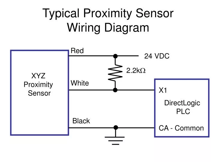
PPT Typical Proximity Sensor Wiring Diagram PowerPoint Presentation, free download ID6729640
2 Wire Proximity Sensor Wiring Diagrams are the diagrams used to wire up two-wire proximity sensors, which are the most common type of sensor used for industrial automation applications. This type of sensor is capable of detecting the presence of a target object within a certain range and can provide precise measurements of its position.

How to wiring proximity sensors with PLC Omron CP1E and create create project with CXProgrammer
Ig5953 Ifm Electronic Inductive Barrel Style Proximity Sensor Pnp Npn Output 8 Mm Detection Ip68 M18 X 1 Rs Components. If5645 Ifm Electronic M12 X 1 Inductive Proximity Sensor Barrel Pnp Npn Output 2 Mm Detection Ip67 285 706 Rs Components. Ifm Efector Im0011 Block Inductive Proximity Sensor 15 Mm Detection Range 20 To 250 Vac Dc Ip65 Allied.
4 Wire Oxygen Sensor Wiring Diagram Cadician's Blog
Electrical wiring of sensors What you need to know about wiring of sensors Which output type do you need: PNP or NPN?What is the difference between normally open and normally closed? We will explain it for you. PNP output (Sourcing output +24 V DC)

2 Wire Proximity Sensor Wiring Diagram Free Wiring Diagram
A 3 wire proximity sensor wiring diagram is a valuable resource for any electronics engineer. It will help you properly install, wire and test a sensor. Using a wiring diagram saves time when troubleshooting any electrical problems, as it provides the exact point of connection for each component.
Proximity Sensor Wiring Diagram Collection
Sensor 1 is reading 0v which is correct. Sensor 2 and 3 read 8.33v and 25v respectively. Since sensors 2 and 3 are trigger, I would've thought those readings would've been the voltage applied across them (15v and 11v) with slightly lower values due to resistance.

[DIAGRAM] 6 Wire Wiring Diagram Free Download
Welcome to Electro Engage! 🚀 In this comprehensive video, we dive deep into the 2 Wire Proximity Sensor Connection for 3-Phase Motors - an essential tool in.

3 Wire Proximity Sensor Wiring Diagram Wiring Diagram
PNP vs NPN Sensors: How to Choose the Right Sensor for Your Application, and it's working and wiring In this video, we will be discussing the about PNP and.

2wire Proximity Sensor Wiring Diagram Wiring Diagram
By Lambda Geeks Proximity sensors are widely used in various industries and applications to detect the presence or absence of objects within a certain range. These sensors work by emitting electromagnetic fields or beams and measuring the changes in the field or beam when an object is detected.

21 Beautiful Proximity Sensor Wiring Diagram
How to wiring (NPN and PNP) 3 wire proximity sensor, and how to identify if PNP or NPN in a circuit diagram.what is a proximity sensor, how does it work a 3w.